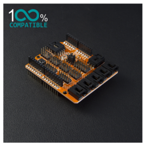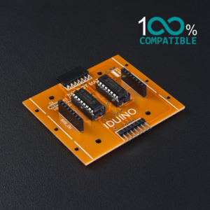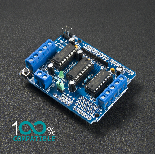
Iduino Servo & Motor Controller L293D
The Iduino Servo & Motor Controller L293D is a high-voltage, high-current, 4-channel driver capable of controlling DC motors, stepper motors, and servos. This module uses the L293D chip, which is an H-Bridge designed to provide bi-directional control over motors. With the ability to supply up to 600mA per channel and handle motors up to 25V, it’s perfect for running large motors. It supports 2 servos, 4 DC motors, or 2 stepper motors with precise control over speed and direction. The controller includes thermal protection and separate logic/motor supplies.
Features:
- 2 interface for 5V Servo connected to the Arduino’s high-resolution dedicated timer – no jitter
- Can drive 4 DC motors or 2 stepper motors or 2 Servo
- Up to 4 bi-directional DC motors with individual 8-bit speed selection
- Up to 2 stepper motors (unipolar or bipolar) with single coil, double coil or interleaved stepping
- 4 H-Bridges: per bridge provides 0.6A (1.2A peak current) with thermal protection, can run motors on 4.5V to 25V DC
- Pull down resistors keep motors disabled during power-up. 2 external terminal power interface, for separate logic/motor supplies
What pins are used on the motor shield?
All 6 analog input pins are available. They can also be used as digital pins (pins #14 thru 19)
Digital pin 2, and 13 are not used.
The following pins are in use only if the DC/Stepper noted is in use:
Digital pin 11: DC Motor #1 / Stepper #1 (activation/speed control)
Digital pin 3: DC Motor #2 / Stepper #1 (activation/speed control)
Digital pin 5: DC Motor #3 / Stepper #2 (activation/speed control)
Digital pin 6: DC Motor #4 / Stepper #2 (activation/speed control)
The following pins are in use if any DC/steppers are used
Digital pin 4, 7, 8 and 12 are used to drive the DC/Stepper motors via the 74HC595 serial-to-parallel latch
The following pins are used only if that particular servo is in use:
Digitals pin 9: Servo #1 control
Digital pin 10: Servo #2 control